[Note, 24 Feb 10: I've just updated my schematic to fix an error. I'd forgotten to break the original connection from V6 pin 5 to ground. That's now been fixed, and I've updated the schematic revision to Rev. 2. I've also added Notes 5 & 6 at the end of this post. - Jeff]
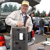
 (Cheyenne, now with knob and case. HP-20 power supply by the side)
In my earlier Cheyenne posting (click here) I described the modifications I'd made to the Cheyenne's audio stage to improve audio fidelity. This new post will describe some additional changes I've made since that original post, and I'll also update the MT-1 schematic.
I had been noticing that, during transmit, the 6CL6 tube (driven by the 6AU6 VFO) was getting very hot. I temporarily put a 0.5 ohm resistor in its plate circuit so that I could measure its plate current, and I discovered that it was drawing on the order of 64 mA, which, given its plate voltage of 322 volts, was 21 watts of plate dissipation.
The 6CL6 has a maximum plate dissipation of 7.5 watts, so this was far beyond where it should operate.
I took a look under the chassis and immediately noticed that the 6CL6's screen-grid resistor was 6.8K, rather than the 27K shown on my Heathkit schematic. But, when I referred to the assembly manual for verification, the instruction for the installation of this resistor describes a 6.8K resistor. In other words, the assembly manual's instructions match the wiring of my transmitter, whereas the schematic does not match the wiring.
I decided that the easiest way to lower the 6CL6's plate current would be to lower its screen-grid voltage. To do this, I added 47K ohms in series with the existing 6.8K ohm resistor. This drops the plate current to about 23 mA on 80 meters (7.4 watts plate dissipation) and 15 mA on 40 meters (4.9 watts).
Also, I found that I needed to change the value of the screen-grid resistor to the 6146 PA. I had initially changed this to 50K (please refer to my first post), but, after lowering the 6CL6 plate current (and replacing the 6146 tube) I found I needed to double this value to 100K ohms to give me my desired "sweet spot" of 10 watts out when the pot has been adjusted so that there's about 6 volts on the cathode of the first stage of the 6DE7 modulator (V6 pin 5).
While making these changes I also discovered other differences between the wiring of the Cheyenne's RF stages and the schematic. Again, the wiring within my Cheyenne corresponds to the instructions in my assembly manual, rather than the schematic
So I've modified the schematic to include my mods as well as the differences that I've found (to date) between it and the actual transmitter wiring (as described in my assembly manual). My mods are in red, and the wiring differences are in green:
These differences between the schematic and the manual are:
- V2 screen-grid resistor is actually 6.8K, not 27K.
- V3 screen-grid resistor is actually 4.7K, not 27K.
- The tuning circuit for the PA grid is not a parallel L-C circuit, but instead it is a pi-network. 300 volts DC is fed to the plate of V3 (5763) via a 2.5 mH inductor. The signal from this plate is then coupled to the input of the pi-network via a 6.8 pF cap, and the output of the pi-network's inductor is directly connected to the PA grid (V4 pin 5), to which a grounded 47 pF cap is also attached.
Additional Notes:
1. I used a Krylon spray-paint that I found at the local hardware store to repaint the Cheyenne's cabinet. It's Krylon Indoor/Outdoor Gloss Hunter Green. This isn't an exact match for the original Heathkit paint (which is slightly lighter and, in my opinion, contains a bit more blue), but I find it is close enough for my tastes.
2. With a new 6146W and the 6CL6 mods, for 10 watts out on 80 meters, the 6146 Screen Grid voltage is now about 94 volts (compared to the (roughly) 52 volts I describe in my original Cheyenne posting (for 9 watts out)).
3. There is a change to my tuning instructions in my original post: Now, when tuning, I peak the Drive control (grid) to give me maximum power out. Note that there may be two peaks (one lower than the other) as you rotate the Drive control. On 80 meters I get max power out with a grid current of about 2 mA, which is not the max grid current that I can get by rotating the Drive control.
4. The audio, in my opinion, sounds quite nice. I'm using a Heil PR-40 mic that is equalized using a Behringer 802 mixer/equalizer (the PR-40 the highs and mids need to be accentuated), and the Behringer level is set such that the Cheyenne's Audio pot is at about 2 to 2.5 on its scale. The Cheyenne's RF output is then fed into an Ameritron AL-811 linear.
5. If your power supply supplies a different high-voltage than my HP-20 (660 VDC), you may need to make some component value changes. For example, if you find that the final resistance of the 25K pot (from V6.5 to ground), after adjustment, is very small, you should increase the capacitance value of the 1uF cap that parallels it, otherwise you could lose low-frequency response in your audio. Or, if you want to keep this pot at roughly mid-level, you may want to try lowering the resistance of the screen-grid resistor to give you more output power.
My recommendation would be that you adjust the pot to give you (very roughly) 6 volts from V6.5 to ground, and then, if you don't have adequate power out, adjust the PA screen-grid resistor value. (If the voltage at V6.5 is too small, you run the risk of clipping the positive peaks of the audio at the grid of V6, which is why I recommend that the voltage at the cathode be about 6 volts).
6. By the way -- placing the 25K pot in the first section of V6, rather than the second section of V6 ( where others have placed it when modifying DX-60's), means you don't need to have a high-power pot (which you do if you place this pot in the cathode-circuit of the other half of V6). Instead, with it connected to V6.5, this pot adjusts the operating point of the first half of V6 (thus there's a low voltage across it, about 6 volts). Because the plate of this first half of V6 is dc-coupled to the grid of the second half of the tube, changing the cathode-voltage at V6.5 also changes the cathode voltage of the second section of V6, and thus changes the screen voltage to the PA.
(Raising the voltage at the V6.5 cathode drives this section towards cut-off (lowering plate current), which raises the voltage at the corresponding plate, V6.6, and thus the voltage to the grid of the second section. Raising this grid voltage means more current will flow through the second section of V6, which raises the voltage at the second cathode and thus raises the PA screen voltage.)
7. And as a reminder, my earlier posting on the Cheyenne is here.
8. An audio clip of my Cheyenne driving an Ameritron AL-811 amplifier can be found here.
Standard Caveat...
I hope you find this information useful, but please, use these modifications at your own risk -- although they worked for me, I cannot guarantee that they'll work for you. (After all, I could have made a mistake in transposing them from my lab notebook to this post, or there may be other problems in my rig that make its performance different from yours. So always verify for yourself that the changes have improved, rather than worsened, performance!)
If you do find any errors, or if you have any questions, please let me know. Thanks!
- Jeff, K6JCA


3 comments:
Very Nice Job on the MT-1 Mod's.
Great info for any ham who wants to rework the old ring to a quality sounding AM signal.
Enjoyed your article very much.
We like your Bird Street Background music as well and....small world....
One of my good "CB friends" (yes I do a bit of CB-AM now and then) Jimmy Morello has a show on Bird Street on Saturday night called "Let's have a Party"
He is an expert on the Blues and I call in (Bird Street LL) often during his show to request "The Good Doctor" (his CB handle) to play some quality old "Chicago Blues". I am a Harmonica amateur musician myself as well as guitar. (see my QRZ profile)
Jimmy always refers to me on the FM air as "Bryan from Chicago" as the call in request.
Check out his program some time. 6-8PM Sat Night.
http://www.radiobirdstreet.org/programs.html
73 - WB9MCW - Bryan in Chicagoland.
Sorry so silly of me --
I was still logged into Radio Bird Street (from last night - listening to Jimmy's show)and wrongly thought you were streaming the Bird Street audio to your blog site somehow --
I did not look up your location on QRZ yet and thought you were from the N. Cali area because the "Bird Street" streaming was coming out of my headphones while I was reading your blog on the Cheyenne.
Pretty funny eh?
Oh well that is what happens with all this new technology sometimes.
We see you are in Texas anyway -- too funny --- I assumed from your call (and the Bird Street still playing) you were in N. Cali--
At any rate the reason I came to your site was a Google search on the MT-1 because I used to run one as my TX for CW on my Novice Station back in 1972 and have always had a "soft spot" for the old transmitter. My RX was a HR-10.
With the upgrade to "General" we bought a TR-3 for our next ham station.
Well 73 again and great job on the old Cheyenne Mod's. WB9MCW
Hi Bryan, thanks for the comments! I'm glad you enjoyed the MT-1 mods.
Actually, I do live in Northern California (rather than Texas). But I'm unfamiliar with Bird St. music...sounds interesting. May need to check it out one of these days.
Many thanks for stopping by the blog!
73,
- Jeff, k6jca
Post a Comment