In this post I will:
- Determine the capacitor voltage rating
- Calculate the maximum RMS current through each capacitor
- Select the type of capacitors to use
- Estimate capacitor ESR
- Estimate capacitor power dissipation (using the max RMS current through each capacitor and its estimated ESR).
To recap the specification from the first post, I'm limiting low-frequency operation to 3.5 MHz. Also, I am assuming that the worse-case load will have an SWR of 10:1 and that it could lie anywhere on a Smith Chart's "Circle of Constant SWR" for an SWR of 10.
Given these constraints, I calculated the following maximum L and C requirements for a lowpass L-Network, per band:
(click on image to enlarge)

So I'll need 2730 pF (and max inductance is 6.82 uH) to match the anywhere along the circumference of the 10:1 Smith Chart SWR-circle at 3.5 MHz
Also, I want to know the current and voltage specifications that the capacitance and inductance must meet.
To accomplish this, I created an EXCEL spreadsheet to step around a Smith Chart's "circle of constant SWR" (which determines the range of possible load impedances) and, given each load impedance, the value of the matching components to match that load impedance, and a given transmit power, I calculated peak and average voltages and currents for the matching network's components.
From the range of calculated values, the maximum peak and maximum average currents and voltages are tabulated in the table, below. Note that they assume an average power of 200 watts (e.g. AM Carrier), a peak power of 800 watts (e.g. SSB peak), and a maximum SWR of 10:1, and thus the peak voltage across the L-network capacitance is 880 volts.

Let's round the Vpeak requirement of 880 up to 1000 volts (to give us a bit of headroom). Therefore...
Capacitor Voltage Specification: Vpeak of 1000 VDC (min).
And from the table:
Capacitor Current Specification: Irms of 6.9 A
But this last spec is a bit tricky -- the total capacitance is made up of capacitors connected in parallel, so this current might be divided through a number of parallel caps.
I'll calculate the maximum current in each cap in just a bit, but before I do, I first want to select the values of caps that I'll use, because these values will determine the amount of current that flows through each.
Although I have a box of miscellaneous-valued high-voltage doorknob caps, their ESR is unknown. So rather than spending time sorting them and measuring their Q's, why not use high-Q SMD ceramic capacitors? I used these in my class E/F amplifier (http://k6jca.blogspot.com/2011/01/80-meter-class-ef-rf-amplifier.html), why not use them again? And I noticed that Elecraft also uses SMD caps in their KAT500 auto-tuner, which is very good internal tuner-loss (see: http://www.ad5x.com/images/Presentations/KAT500Review.pdf).
Well, that was an easy decision!
There are a number of manufacturers who make high-Q ceramic chip caps for RF applications, They include:
So Johanson is out.
AVX prices are listed at around $17 per cap, while Vishay is much less expensive at about $2 per cap.
Given the significant cost difference, I think Vishay might be the way to go. But I need to check their specs.
Vishay's "Quad Hifreq" Series datasheet is available here: http://www.vishay.com/docs/45221/quadhifreq.pdf)
Digikey carries this series in 0505 and 1111 case sizes. Only the 1111 case size has the voltage rating that's at least 1000 VDC (ratings are 1500 VDC for values below 100 pF and 1000 VDC for 100, 120, and 180 pF).
So I'll focus on the caps in the 1111 package size. Here are their specs, from the Vishay data sheet:
ESR:

Well, this looks pretty good (but I'll do some more checking a bit later in this post -- I'd like to get an estimate of power loss in my application). At 30 MHz, the ESR approximately is:
Here's the chart for Self-Resonant Frequency (SRF):

No issue here. SRF is well above 30 MHz (and the SRF for the capacitor values that I'll be using (see further below) is well above 400 MHz)!
Now, Current Rating:

This looks pretty good -- max current is above 10 Amps. I'm going to assume that the 10 Amp limit is good down to 3 MHz. (By the way -- the "diagonal" limit in the template above will be automatically met if I keep the cap voltages below their Vpk (i.e. Vdc) specification).
From my table earlier in this post, I know that the max current through the L-Network capacitance will 6.9 amps (for an SWR of 10 at 200 watts) so there should be plenty of margin. But we'll delve further into this a bit later in this post.
And finally, Temperature Coefficient:
Very good!
For completeness, here's Q versus Frequency from the datasheet. I don't know how I'd use this, though, because it just seems to duplicate the ESR spec (Q = Xc/ESR).

Everything looks good so far. But what capacitor values should I use?
To ensure that I can match any load with a 10:1 SWR, I need a maximum capacitance of around 2700 pF with a voltage rating of at least 1000 VDC. But at this voltage rating, the three largest values in this series that Digikey stocks are: 100, 120, and 180 pF.
But I can create larger cap values by connecting 180 pF caps in parallel. So, if I use 180 pF as the basis for the larger caps (and if I also divide 180 pF down by powers of two), I get the following 8 values of capacitance:
These values sum to 2869 pF. Great!
And the minimum step size of 11 pF should give me adequate coverage on 30 MHz (but I'll need to verify this later, after I've selected my inductors).
Note that none of the four smaller values are standard capacitance values. But they are close to standard values (and of course the fractional parts of these values are unimportant). If standard values aren't close enough (i.e. off by more than a few pF), I can parallel two smaller values to make a value sufficiently close to what is required.
And as I mentioned, I'll create the 360, 720, and 1440 pF caps by paralleling 180 pF caps. There's an advantage to doing this -- paralleling these caps will effectively lower the ESR (and thus power dissipation).
Delving deeper into capacitor current...
Let's get back to checking capacitor current (because I'd like to estimate the power dissipation).
For each of the 8 capacitor values that I've selected, its current must fit within the Current template shown in the Vishay "Current Chart":

For each capacitor I've calculated (using Excel and Matlab) its maximum RMS current (Irms) on each of the ham bands, for an SWR of 10:1 and an input power of 200 watts.
Here's a plot showing these currents at 3.5 MHz as we move the load around a Smith Chart's "Circle of Constant 10:1 SWR" :

Note that the max current for, say, the 1440 pF cap does not occur at the same load as the max current for, say, the 720 pF cap.
And here are the capacitor currents at 28 MHz for the same 10:1 SWR and the same power:

I've listed these maximums in the table below.

If you compare the currents in the table with the currents shown in the graph, the maximum capacitor currents are easily within the capacitors' current ratings.
Let's continue on to my goal of estimating power dissipation...
Estimating capacitor ESR and Power Dissipation
First, I need to determine the ESR for each capacitor. Let's use the ESR graph from earlier in this post.

10 MHz is the graph's lowest frequency. But I'll assume that the ESR lines remain linear down to 1 MHz (the next decade down) on the log-log scale, so I will extend the graph down to 1 MHz (by hand), which allows me to estimate ESR for any of the frequencies that interest me.
Here are my estimates:

To create this table I've assumed:

It should be obvious, but please note: you cannot simply sum these losses to get the total power loss due to capacitor ESR at a given frequency. Each capacitor's max current occurs at a different load (see the earlier graphs of capacitor current versus angle of reflection coefficient). This table simply identifies the worse-case loss we should expect for any given cap on any given band.
So, from the table above, my estimated worse-case power dissipation is about 1.6 watts in the 180 pF cap (at 30 MHz). This is not too bad, but it might be worthwhile to try to reduce its ESR even further by paralleling smaller-valued caps of the same 1111 package size. I'll have to do some experimentation after my caps arrive...
Summary:

I want to stress -- these caps might change (and probably will) as I get further into the design process. This is my first cut at their selection. I'd like to try either the ATC caps (their 700C or 800C series) or the AVX caps (their HQCC series). The ATC 700C and AVX HQCC series are in larger cases sizes (0.23 x 0.25 inches) and they have similar characteristics. For example, at 30 MHz their ESRs are:

(These numbers are from eyeballing the graphs in the datasheets, so I could be slightly off).
OK, this ends Part 2 of this series. Part 3 will deal with the L-Network inductors. It can be found here: http://k6jca.blogspot.com/2015/06/antenna-auto-tuner-design-part-3.html
The previous post, Part 1 -- Preliminary Specifications, is here: http://k6jca.blogspot.com/2015/06/antenna-auto-tuner-design-part-1.html
Links to my blog posts in this Auto-tuner series:
Part 1: Preliminary Specification
Part 2: Network Capacitor Selection
Part 3: Network Inductor Selection
Part 4: Relays and L-Network Schematic (Preliminary)
Part 5: Directional Coupler Design
Part 6: Notes on Match Detection
Part 7: The Build, Phase 1
Part 8: The Build, Phase 2 (Integration of Match Detection)
Part 9: The Build, Phase 3 (Incorporating a Microcontroller)
Part 10: The Final Schematics
Resources:
Datasheet, Capacitor, Vishay, Quad Hifreq: http://www.vishay.com/docs/45221/quadhifreq.pdf
Datasheet, Capacitor, AT Ceramics, 700C series: http://www.atceramics.com/UserFiles/700c.pdf
Datasheet, Capacitor, AVX, HQCC series: http://www.avx.com/docs/Catalogs/hi-q.pdf
My Other Tuner posts:
A quick tutorial on Smith Chart basics: http://k6jca.blogspot.com/2015/03/a-brief-tutorial-on-smith-charts.html
The L-network: http://k6jca.blogspot.com/2015/03/notes-on-antenna-tuners-l-network-and.html
A correction to the usual L-network design constraints: http://k6jca.blogspot.com/2015/04/revisiting-l-network-equations-and.html
A look at highpass T-Networks: http://k6jca.blogspot.com/2015/04/notes-on-antenna-tuners-t-network-part-1.html
More on the W8ZR EZ-Tuner: http://k6jca.blogspot.com/2015/05/notes-on-antenna-tuners-more-on-w8zr-ez.html (Note that this tuner is also discussed in the highpass T-Network post).
The Elecraft KAT-500: http://k6jca.blogspot.com/2015/05/notes-on-antenna-tuners-elecraft-kat500.html
The Nye-Viking MB-V-A and the Rohde Coupler : http://k6jca.blogspot.com/2015/05/notes-on-antenna-tuners-nye-viking-mb-v.html
Standard Caveat:
As always, I might have made a mistake in my equations, assumptions, drawings, or interpretations. If you see anything you believe to be in error or if anything is confusing, please feel free to contact me or comment below.
And so I should add -- this design and any associated information is distributed in the hope that it will be useful, but WITHOUT ANY WARRANTY; without even the implied warranty of MERCHANTABILITY or FITNESS FOR A PARTICULAR PURPOSE.
(click on image to enlarge)

Let's round the Vpeak requirement of 880 up to 1000 volts (to give us a bit of headroom). Therefore...
Capacitor Voltage Specification: Vpeak of 1000 VDC (min).
And from the table:
Capacitor Current Specification: Irms of 6.9 A
But this last spec is a bit tricky -- the total capacitance is made up of capacitors connected in parallel, so this current might be divided through a number of parallel caps.
I'll calculate the maximum current in each cap in just a bit, but before I do, I first want to select the values of caps that I'll use, because these values will determine the amount of current that flows through each.
Although I have a box of miscellaneous-valued high-voltage doorknob caps, their ESR is unknown. So rather than spending time sorting them and measuring their Q's, why not use high-Q SMD ceramic capacitors? I used these in my class E/F amplifier (http://k6jca.blogspot.com/2011/01/80-meter-class-ef-rf-amplifier.html), why not use them again? And I noticed that Elecraft also uses SMD caps in their KAT500 auto-tuner, which is very good internal tuner-loss (see: http://www.ad5x.com/images/Presentations/KAT500Review.pdf).
Well, that was an easy decision!
There are a number of manufacturers who make high-Q ceramic chip caps for RF applications, They include:
- AT Ceramics (ATC)
- AVX
- Johanson
- Vishay
So Johanson is out.
AVX prices are listed at around $17 per cap, while Vishay is much less expensive at about $2 per cap.
Given the significant cost difference, I think Vishay might be the way to go. But I need to check their specs.
Vishay's "Quad Hifreq" Series datasheet is available here: http://www.vishay.com/docs/45221/quadhifreq.pdf)
Digikey carries this series in 0505 and 1111 case sizes. Only the 1111 case size has the voltage rating that's at least 1000 VDC (ratings are 1500 VDC for values below 100 pF and 1000 VDC for 100, 120, and 180 pF).
So I'll focus on the caps in the 1111 package size. Here are their specs, from the Vishay data sheet:
ESR:
(click on image to enlarge)

Well, this looks pretty good (but I'll do some more checking a bit later in this post -- I'd like to get an estimate of power loss in my application). At 30 MHz, the ESR approximately is:
10 pF ESR @ 30 MHz = 0.25 ohms
180 pF ESR @ 30 MHz = 0.04 ohms
Here's the chart for Self-Resonant Frequency (SRF):
(click on image to enlarge)

No issue here. SRF is well above 30 MHz (and the SRF for the capacitor values that I'll be using (see further below) is well above 400 MHz)!
Now, Current Rating:
(click on image to enlarge)

This looks pretty good -- max current is above 10 Amps. I'm going to assume that the 10 Amp limit is good down to 3 MHz. (By the way -- the "diagonal" limit in the template above will be automatically met if I keep the cap voltages below their Vpk (i.e. Vdc) specification).
From my table earlier in this post, I know that the max current through the L-Network capacitance will 6.9 amps (for an SWR of 10 at 200 watts) so there should be plenty of margin. But we'll delve further into this a bit later in this post.
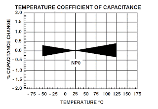
And finally, Temperature Coefficient:
(click on image to enlarge)

Very good!
For completeness, here's Q versus Frequency from the datasheet. I don't know how I'd use this, though, because it just seems to duplicate the ESR spec (Q = Xc/ESR).
(click on image to enlarge)

Everything looks good so far. But what capacitor values should I use?
To ensure that I can match any load with a 10:1 SWR, I need a maximum capacitance of around 2700 pF with a voltage rating of at least 1000 VDC. But at this voltage rating, the three largest values in this series that Digikey stocks are: 100, 120, and 180 pF.
But I can create larger cap values by connecting 180 pF caps in parallel. So, if I use 180 pF as the basis for the larger caps (and if I also divide 180 pF down by powers of two), I get the following 8 values of capacitance:
1440 (8 x 180)
720 (4 x 180)
360 (2 x 180)
180 (1 x 180)
90
45
22.5
11.25
These values sum to 2869 pF. Great!
And the minimum step size of 11 pF should give me adequate coverage on 30 MHz (but I'll need to verify this later, after I've selected my inductors).
Note that none of the four smaller values are standard capacitance values. But they are close to standard values (and of course the fractional parts of these values are unimportant). If standard values aren't close enough (i.e. off by more than a few pF), I can parallel two smaller values to make a value sufficiently close to what is required.
And as I mentioned, I'll create the 360, 720, and 1440 pF caps by paralleling 180 pF caps. There's an advantage to doing this -- paralleling these caps will effectively lower the ESR (and thus power dissipation).
Delving deeper into capacitor current...
Let's get back to checking capacitor current (because I'd like to estimate the power dissipation).
For each of the 8 capacitor values that I've selected, its current must fit within the Current template shown in the Vishay "Current Chart":
(click on image to enlarge)

For each capacitor I've calculated (using Excel and Matlab) its maximum RMS current (Irms) on each of the ham bands, for an SWR of 10:1 and an input power of 200 watts.
Here's a plot showing these currents at 3.5 MHz as we move the load around a Smith Chart's "Circle of Constant 10:1 SWR" :
(click on image to enlarge)

Note that the max current for, say, the 1440 pF cap does not occur at the same load as the max current for, say, the 720 pF cap.
And here are the capacitor currents at 28 MHz for the same 10:1 SWR and the same power:
(click on image to enlarge)

I've listed these maximums in the table below.
(click on image to enlarge)

If you compare the currents in the table with the currents shown in the graph, the maximum capacitor currents are easily within the capacitors' current ratings.
Let's continue on to my goal of estimating power dissipation...
Estimating capacitor ESR and Power Dissipation
First, I need to determine the ESR for each capacitor. Let's use the ESR graph from earlier in this post.
(click on image to enlarge)

10 MHz is the graph's lowest frequency. But I'll assume that the ESR lines remain linear down to 1 MHz (the next decade down) on the log-log scale, so I will extend the graph down to 1 MHz (by hand), which allows me to estimate ESR for any of the frequencies that interest me.
Here are my estimates:
(click on image to enlarge)

To create this table I've assumed:
- The ESR of the 11 pF cap is about the same as the 10 pF cap, which is available via the graph.
- The 22 pF cap will be two 11 pF caps in parallel. Thus, the combined ESR is half the 10 pF ESR.
- Ditto for the 45 pF cap, but with four 11 pF caps in parallel.
- The ESRs of the 90 pF cap are a guess, which is why they are red.
- The 180 pF cap ESR is from the graph.
- The ESRs of the 360, 720, and 1440 nF caps, being composed of paralleled 180 pF caps, are just the 180 pF ESR divided by either 2, 4, or 8, depending upon the number of paralleled caps.
(click on image to enlarge)

It should be obvious, but please note: you cannot simply sum these losses to get the total power loss due to capacitor ESR at a given frequency. Each capacitor's max current occurs at a different load (see the earlier graphs of capacitor current versus angle of reflection coefficient). This table simply identifies the worse-case loss we should expect for any given cap on any given band.
So, from the table above, my estimated worse-case power dissipation is about 1.6 watts in the 180 pF cap (at 30 MHz). This is not too bad, but it might be worthwhile to try to reduce its ESR even further by paralleling smaller-valued caps of the same 1111 package size. I'll have to do some experimentation after my caps arrive...
Summary:
- The capacitor SRF, Max Current, Peak Voltage, and Temperature Coefficient specs all meet my requirements.
- I've tweaked the values to correspond those available from Digikey
(click on image to enlarge)

I want to stress -- these caps might change (and probably will) as I get further into the design process. This is my first cut at their selection. I'd like to try either the ATC caps (their 700C or 800C series) or the AVX caps (their HQCC series). The ATC 700C and AVX HQCC series are in larger cases sizes (0.23 x 0.25 inches) and they have similar characteristics. For example, at 30 MHz their ESRs are:

(These numbers are from eyeballing the graphs in the datasheets, so I could be slightly off).
OK, this ends Part 2 of this series. Part 3 will deal with the L-Network inductors. It can be found here: http://k6jca.blogspot.com/2015/06/antenna-auto-tuner-design-part-3.html
The previous post, Part 1 -- Preliminary Specifications, is here: http://k6jca.blogspot.com/2015/06/antenna-auto-tuner-design-part-1.html
Links to my blog posts in this Auto-tuner series:
Part 1: Preliminary Specification
Part 2: Network Capacitor Selection
Part 3: Network Inductor Selection
Part 4: Relays and L-Network Schematic (Preliminary)
Part 5: Directional Coupler Design
Part 6: Notes on Match Detection
Part 7: The Build, Phase 1
Part 8: The Build, Phase 2 (Integration of Match Detection)
Part 9: The Build, Phase 3 (Incorporating a Microcontroller)
Part 10: The Final Schematics
Resources:
Datasheet, Capacitor, Vishay, Quad Hifreq: http://www.vishay.com/docs/45221/quadhifreq.pdf
Datasheet, Capacitor, AT Ceramics, 700C series: http://www.atceramics.com/UserFiles/700c.pdf
Datasheet, Capacitor, AVX, HQCC series: http://www.avx.com/docs/Catalogs/hi-q.pdf
My Other Tuner posts:
A quick tutorial on Smith Chart basics: http://k6jca.blogspot.com/2015/03/a-brief-tutorial-on-smith-charts.html
The L-network: http://k6jca.blogspot.com/2015/03/notes-on-antenna-tuners-l-network-and.html
A correction to the usual L-network design constraints: http://k6jca.blogspot.com/2015/04/revisiting-l-network-equations-and.html
A look at highpass T-Networks: http://k6jca.blogspot.com/2015/04/notes-on-antenna-tuners-t-network-part-1.html
More on the W8ZR EZ-Tuner: http://k6jca.blogspot.com/2015/05/notes-on-antenna-tuners-more-on-w8zr-ez.html (Note that this tuner is also discussed in the highpass T-Network post).
The Elecraft KAT-500: http://k6jca.blogspot.com/2015/05/notes-on-antenna-tuners-elecraft-kat500.html
The Nye-Viking MB-V-A and the Rohde Coupler : http://k6jca.blogspot.com/2015/05/notes-on-antenna-tuners-nye-viking-mb-v.html
Standard Caveat:
As always, I might have made a mistake in my equations, assumptions, drawings, or interpretations. If you see anything you believe to be in error or if anything is confusing, please feel free to contact me or comment below.
And so I should add -- this design and any associated information is distributed in the hope that it will be useful, but WITHOUT ANY WARRANTY; without even the implied warranty of MERCHANTABILITY or FITNESS FOR A PARTICULAR PURPOSE.


No comments:
Post a Comment